Repairing a final drive is a long, complicated, and expensive operation. In the case of faults or wear, the best choice is often replacement with a new final drive: the procedure is simpler and cheaper, and considerably reduces machine down-time.
Let's see in detail how to replace the planetary final drives typically fitted on hydrostatic drive machines, including many tracked vehicles.
After establishing the cause of the failure, fault, or type of wear, the final drive can be replaced starting with the following removal operations:

1. Avoid contaminating the circuit
It is essential to remove any dirt and mud from the area in which the new final drive will be installed, taking particular care with the hydraulic lines. A small volume of fluid should be released to eliminate any particles that might have entered the lines during deinstallation of the old final drive.
It is also important to run a circuit cleaning cycle using a filter kit (a 100 bar 10 micron filter is adequate). Cleaning is achieved by creating a flow loop between the two main outlet and return ports, and simultaneously coupling the second speed pilot line to the drain line. Once this system is connected up, run the motor in both directions for about twenty minutes. At the end of the cleaning procedure it is necessary to replace the hydraulic filters. These should subsequently be replaced periodically every 1000 h of operation.
2. Check the hydraulic fluid level
It is essential to check the hydraulic fluid level after deinstalling the old final drive and running the cleaning cycle. If it is below the minimum, top it up to an adequate level, about half way between the minimum and maximum indicators. Refer to the machine manufacturer's manual of instructions if necessary. Be careful not to mix different types of hydraulic fluid!
After all the checks, the new final drive can be fitted as follows.
Warning: always check that the hydraulic lines are correctly connected! Incorrect connection could damage the hydraulic motor. On some machines it is easy to confuse the second speed attachment with the drain connections (see following paragraph). It can also be difficult to identify which line to connect to which port. It is therefore necessary to be very careful during this stage and check the markings recommended above. If in doubt it is advisable to refer to an expert.

Output and return ports (GREEN): generally indicated as A and B, these are the main input and output lines and generally larger than the others to permit greater flow of hydraulic fluid. In some cases they are the only ports present on the final drive. When a final drive has four ports, A and B are located centrally on the rear collector.
Drain ports (BLUE): most modern final drives have two drain ports, generally positioned alongside the two main ports. They are conventionally identified as C1 and C2. The position of the drain port can be selected by closing one of the two with a cap. It is necessary to use the one positioned highest for the release of air, while the lower one is closed with a cap.
It is important to pay attention to the positioning of the drain cap. Final drives are supplied with one drain port closed with a metal cap and the other closed with a plastic cap. This does not imply that this is the correct installation configuration: depending on the side on which the final drive is fitted, it might be necessary to invert the position of the drain connection. Incorrect connection of the drain line can cause the failure of the group.
Warning: in some cases the blue ports are positioned centrally and not alongside the main green ports! It is essential never to connect the main lines to the blue ports. This error would cause mechanical and hydraulic failure, as well as creating a dangerous situation for operators.
Speed port (RED): normally the speed pilot port is the smallest on the final drive. Depending on the model it can be positioned on the front, side, or back.
Some common port configurations on our final drives are illustrated below:
 |
 |
 |
 |
Before starting up the newly installed final drive it is necessary to check the hydraulic fluid level again. Spillage could have occurred during the deinstallation and fitting procedures. If necessary, top up to the required level.
Warning! It is important to replace the hydraulic fluid after running the new motor for approximately 100 hours. Clean, uncontaminated hydraulic fluid is always essential for the correct operation of the hydraulic motor and it should subsequently be replaced every 500 hours of operation.
The hydraulic fluid changing procedure is as follows:
Now connect a pressure gauge to the circuit and measure the hydraulic fluid pressure, checking that the manufacturer's specifications are respected. After all the connections and necessary checks, the final drive can be started up in forward or reverse drive, keeping the motor running at minimum speed to check for correct operation.
ITR Usco supplies final drives or separate reduction gears at an excellent quality/price ratio, with possible customized solutions and interchangeability, for machines from 0.5 to 50 tons.
Contact us to review our complete range.
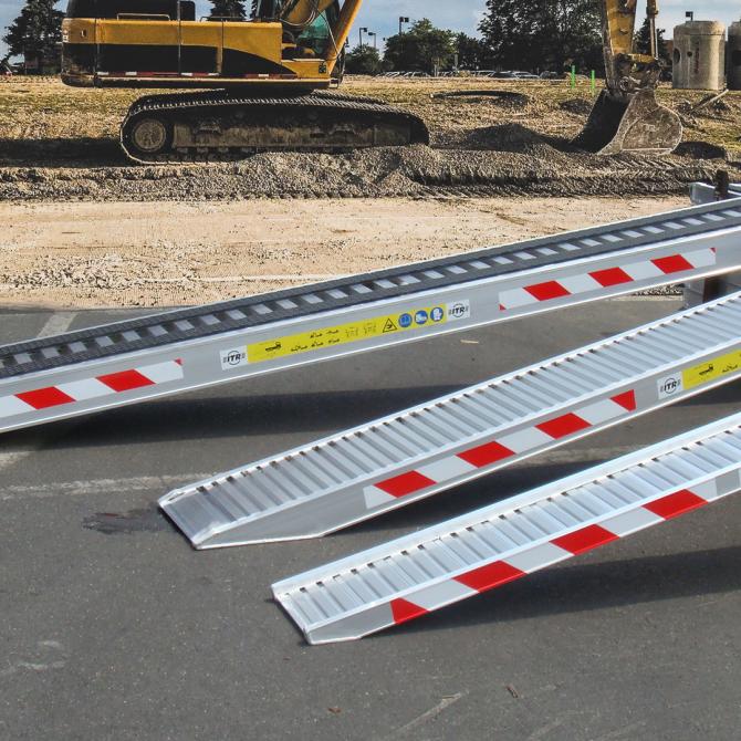
Aluminium ramps are widely used for safely loading and unloading tracked and wheeled machines and eq...
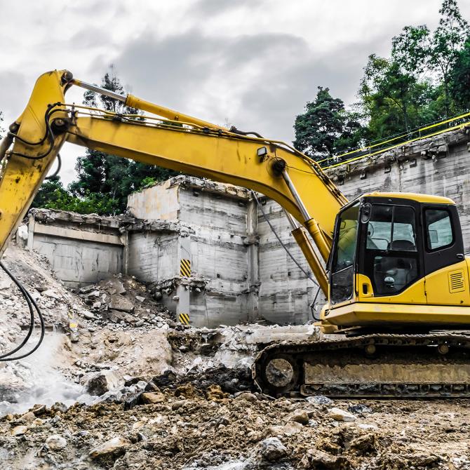
Hydraulic breakers are demolition tools widely used in the earth moving sector and mining industry. ...
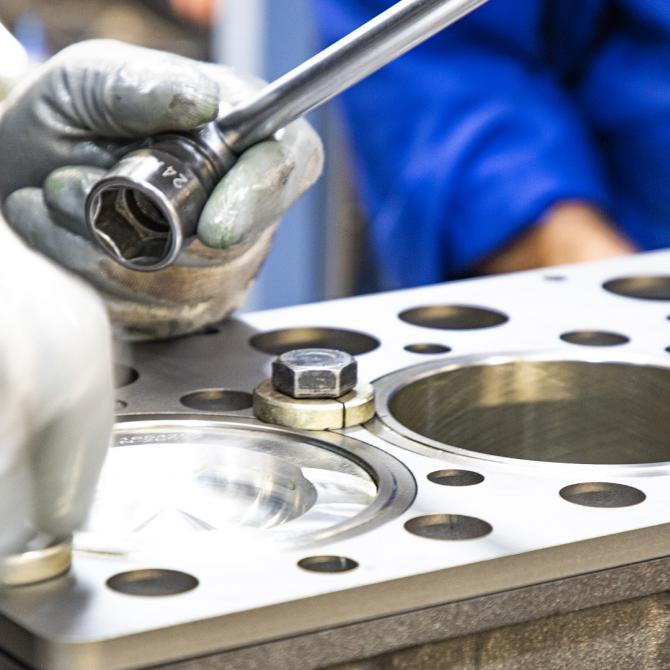
Correct engine operation is one of the fundamental factors for ensuring the performance of earth mov...


 Italy
Italy USA
USA Brazil
 South Africa
 UAE
UAE Australia
 Discover ITR in the world

