Swing circles are used on machines in which the cab needs to rotate relative to the lower machine frame during work operations, for example tracked and wheeled excavators. These bearings are subject to high frequency cyclic loading, tilting moment generated by the projecting arm, and considerable inertial, axial, and radial loading, making it important to take particular care to avoid rapid wear and tear.
Swing circles are very large and are made up of four main components:
Lower toothed ring
Upper ring
Rolling elements (balls arranged in one or two bands, or rollers)
Spacers

Both the rings have grooves, called races, of a size and shape designed to hold the rolling elements and relative spacers. On excavators, the toothed ring of the bearing is fitted to the lower machine body with screw connectors. The upper ring, without teeth, is connected to the frame of the cab. The swing circle allows the two frames to rotate relative to each other, controlling the rotary movement with a reduction gear system. The latter is fitted to the cab frame and has a transmission pinion aligned with the teeth on the bearing in order to drive the movement.

The most frequent cause for replacement of swing circles is breakage of one or more teeth on the lower ring. This renders operation impossible because the number of broken teeth tends to increase rapidly. The main causes lie in deterioration or failure of the drive gear braking system. If this system is not effective, when the direction of movement of the cab changes, the inversion of torque acting on the teeth causes them to flex beyond their design specifications. The risk of breakage is highest when the shovel is loaded and the rotation speed is high.
Another problem that can occur is seizing of the bearing. Despite the high loads to which swing circles are subjected, the ratio between the transverse cross-section and the diameter is relatively small. This makes them deformable if they are not adequately supported. It is therefore important that the connecting structure is sufficiently rigid, the support surfaces are adequately flat, and the fixing system prevents deformation under heavy loading. Failing this, in addition to the risk of the bearing seizing, there is also a risk of permanent damage to the rolling races.
The useful life of swing circles can be increased by following some rules of good practice. These start with the choice of materials during construction, and include correct fitting on the excavator and effective routine maintenance, which can significantly reduce premature wear.
Materials and heat treatments
The choice of materials and heat treatments is critical to achieve strong, durable swing circles, especially as regards the lifespan of the teeth. Normally two types of steel are used: 42CrMo4 hardened with R=90-100 kgf/mm for the internal rings, and C45 hardened with R=70-80 kgf/mm for the external rings.
It is also necessary to include surface heat treatment for the most heavily loaded areas of the bearing, which are the races for the rolling elements, and the teeth of the internal ring. An induction hardening process increases the resistance of the teeth to bending and pitting on the contact surfaces. The rolling races are treated in the same way to counter wear from the continuous transit of the moving parts.
Transport and storage
In order to avoid impact and damage, especially in the radial direction, the swing circle must be enclosed in rigid casing and transported horizontally. During storage the casing and bearing must remain indoors, protected from atmospheric agents that could cause corrosion. When unpacking, it is important to take care not to damage the gaskets and to degrease the bearing with commercial chloride-free thinners since chloride is harmful for the surfaces.
Installing the swing circle
The process of replacing a damaged swing circle includes some preliminary operations for correct installation of the new bearing. When disassembling it is important to:
Eliminate any dirt and deposits from the bearing support surface.
Check the condition of the structure onto which the bearing will be connected (essential for the correct operation and duration of the bearing itself).
Check that the connecting surfaces have not been damaged during machine operation or disassembly (inadequate planarity could cause the bearing to seize).
After these checks the bearing can be positioned on the lower machine frame. For correct and effective orientation follow the indications shown on the bearing. All swing circles have a hardening start and finish transition zone, which is the most fragile area. It is necessary that hardening transition points are located as far as possible from the area of maximum loading during machine operation.
Before starting to fix the bearing to the frame, check that the fixing bolts are compliant with the specifications in the manufacturer's manual. It is also important to lubricate the bolts in advance and use flat, non-elastic washers. Next, lightly tighten the bolts of the first ring (the lower ring andin the order shown in the figure below) to avoid tensions or distortions of the ring itself. Once the bolts are tightened the operation is completed by applying the screw torque levels indicated in the manufacturer's manual, using a torque wrench of adequate capacity.

The eccentricity of the swing circle and the installation of the pinion
Secondly, it is essential to take the eccentricity of the swing circle into account in order to avoid seizing of the drive transmission or premature wear of the teeth. Due to the low thickness/diameter ration, bearing rings tend to become deformed during heat treatment. Although this does not compromise production quality, it does give them a slightly elliptical rather than circular shape.
During installation check the vertical alignment between bearing and pinion. Even if the machine has more than one pinion, the coupling should be at the points of maximum eccentricity of the bearing. The points of greatest eccentricity are indicated on the bearing with three teeth painted yellow. This makes it possible to calibrate the play between the two sets of teeth at the point of maximum distance between the two components. This is achieved by adjusting the play between the sides of the ring teeth and those of the pinion, ensuring that there is at least [(0.05 * M)] mm, with M representing tooth modulus.

After fitting it is advisable to rotate the system a few times to check that the coupling is correct and there is not excessive noise caused by incorrect meshing. Once this has been established and before starting the cab rotation system, grease the teeth, taking care to fully coat the sides of all the teeth.
Finally, it is advisable to measure and record machine play. This is measured using a comparator positioned as shown in the figure between the upper and lower rings, as close as possible to the rolling race to minimise the influence of elastic deformations in the connecting structure. Once the comparator has been positioned and zeroed, bring the machine to a condition of maximum load and measure the variations deriving from play. The highest measured value in the various angular positions represents the initial machine play and this will be the reference value for future measurements, which are required to monitor the condition of the swing circle.

Maintenance
In order to maximise the life of the bearing and keep it operating well, it is necessary to carry out periodic checks on lubrication, tightness of fixing bolts, condition of gaskets, and machine play.
The bearing is supplied with the rolling races pre-lubricated. They should therefore be lubricated after the first 50 hours of work, and then at intervals based on the machine operating conditions (but never longer than every 100 hours of use). In addition, before and after any extended machine stoppages, the swing circle should be greased. The grease should be applied with the bearing in rotation and is complete when grease exudes from the gasket forming a light film.
Throughout the life of a swing circle it is important to conduct visual checks of the condition of the gaskets and replace them if they appear deteriorated or fragile. According to the same maintenance schedule, the sides of the teeth have to be completely coated with grease, spreading it with a brush or spray.
As already mentioned above, it is good practice to measure machine play once a year in order to reveal problems of abnormal wear of the rolling races. The maximum admissible increase depends on a few different factors. These include: the diameter of the bearing, the type and size of the rolling elements (balls or rollers), and the type of use (higher levels of wear might be acceptable if these do not compromise operation). In all cases, when the increase is four times the initial play it is advisable to consider changing the swing circle.
Our bearings are compatible with the main brands and excavator models from 1 to 120 tons, including Caterpillar, Komatsu, Volvo, Hitachi, Doosan, Hyundai, JCB, Bobcat, and John Deere. For more information contact the author of this article.
With an annual production capacity of 60 thousand pumps, including oil and transmission pumps, high ...
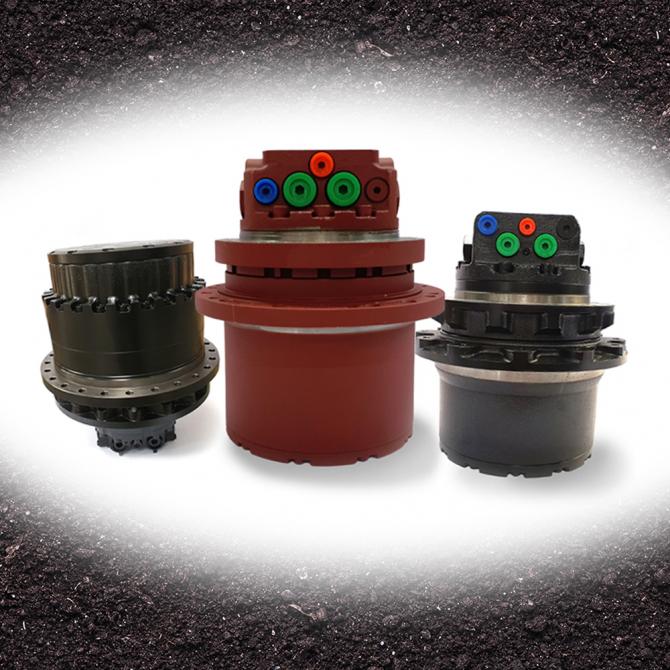
Repairing a final drive is a long, complicated, and expensive operation. In the case of faults or we...
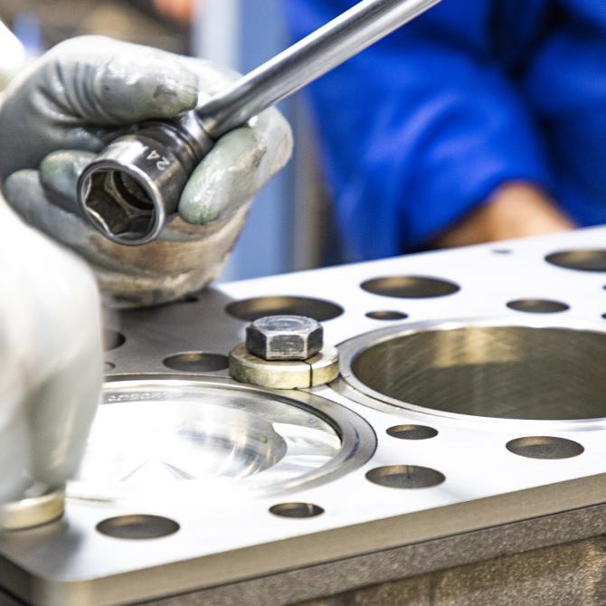
Correct engine operation is one of the fundamental factors for ensuring the performance of earth mov...


 Italy
Italy USA
USA Brazil
 South Africa
 UAE
UAE Australia
 Discover ITR in the world

